1. About LCD (Liquid Crystal Display) Basic Structure

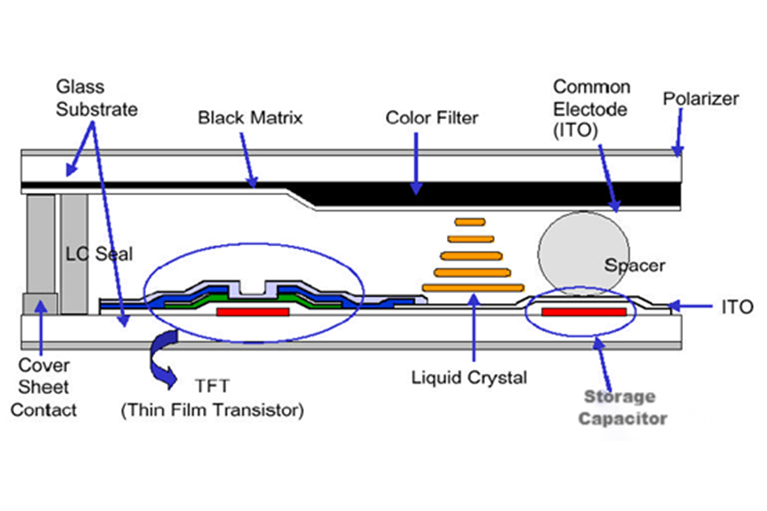
Cover Sheet Contact: The attachment point of the cover sheet
LC Seal: Liquid crystal sealant, anti-liquid crystal leakage
Glass Substrate: A glass substrate for clamping liquid crystals, with TFT on the lower plate and VCOM/CF on the upper plate
TFT (Thin Film Transistor): A thin-film transistor, which is equivalent to a switch, controls the charging and discharging of liquid crystals
Black Matrix: Black matrix, which blocks TFT that does not need to be transparent
Color Filter: A color filter that filters the natural light emitted by the backlight into R/G/B monochromatic light
Liquid Crystal: Liquid crystal, a translucent medium, in which the light source is torsionally transmitted from the lower substrate through the liquid crystal
Common Electrode: Common electrode, which provides VCOM voltage
Spacer: The gap sub, filler, plays a supporting role to prevent the Panel from sinking
Storage Capacitor: A storage capacitor (Cs) that stores electrical charge and keeps the picture displayed
Polarizer: A polarizer that filters out perpendicular light and lets parallel light through
PI Alignment Layer: A alignment film that gives the liquid crystal molecule an initial deflection angle, a pre-inclination angle

2. TFT-LCD basic equivalent circuit
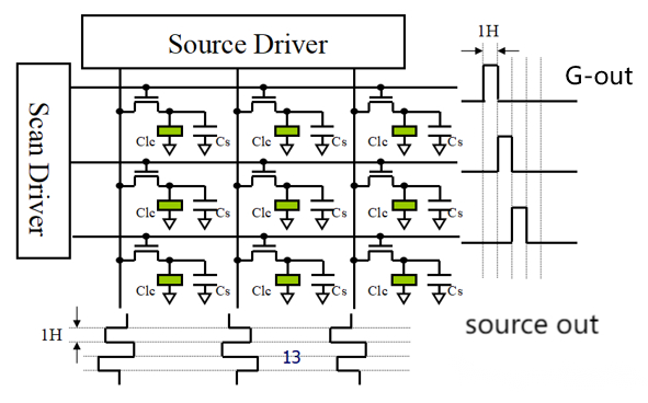
Clc: Liquid crystal capacitance, the equivalent capacitance composed of liquid crystal molecules, controls the deflection angle of liquid crystal molecules by changing the electric field applied at both ends of the Clc (the voltage difference between the voltage provided by the Source Driver and the voltage of VCOM), thereby changing the transmittance of light to present different brightness (gray scale).
Cst: storage capacitor, which is generally much larger than Clc, and is used to maintain the power of Clc; Because the liquid crystal capacitor is relatively small, due to the characteristics of TFT, there is a leakage problem, and the Cst capacitor is required to charge the liquid crystal capacitor in time.
3. Basic working principle: Scan Driver (also known as Gate Driver) turns on TFT line by line according to the timing, and the Source Driver charges Clc and Cst line by line according to the time sequence; After each row is charged, the TFT of the row will be turned off, and the electric field of Clc and Cst will be locked, that is, the screen display of this row will be completed. Perform the above operations for each line in turn to complete the display of the entire frame screen.
Post time: Nov-20-2024
 sales@hemoled.com
 +86 18926513667
